
Use the command LINE, next COPY that construction line to the other corner of the South wall. Draw a construction line projecting the width of the plan, make it generously long. Select the “construction lines” layer, make sure there is a check mark next to the bold layer name, that means you are now drawing on that layer. This method will put the rectangle right in the middle of the wall.)ī.
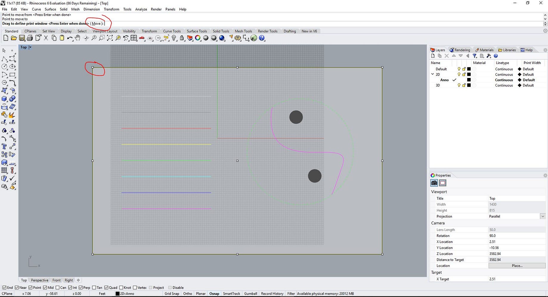
(Note: if the rectangle drawn is not in the middle of the south wall, then select the rectangle, type MOVE, select the middle bottom of the rectangle again, drag it along the bottom of the edge until the End, Int, Mid sign shown and click. Make sure you draw the lines on the corresponding layer. We want to snap the midpoints on the rectangles for the openings to the midpoints of the walls in plan. Center both openings on their respective walls. Use RECTANGLE and select 3Point by clicking on it in the command line or typing “P” after you have started the RECTANGLE command. Now, draw a 36” wide door in plan on the South orientation and a 48” wide window on the East orientation. Turn on “mid,” “end,” and “int” in the bottom of the Rhino window. First, create two sublayers-door and window-under the “plan” layer by either right-clicking on the “plan” layer and selecting “new sublayer” or by clicking on the icon at the top of the layers box. When changing the distance of the offset, type in your desired distance (8”) into the command line and press the “enter” key or press space bar or right click, all of these actions equate to pressing the “enter” key on your keyboard. To change any of these options for command, click on the option in the command line and it will activate for changes or notice which letter is underlined in the command line and simply type that letter. (Note: the options of distance and corner on OFFSET are the two most important input for operation. OFFSET rectangle 8” towards the interior of the rectangle. Select the object and use the window to change its properties. Make sure you drew the curve on the right layer, otherwise you can change its properties with the “object properties” window, type PROPERTIES. Use the command RECTANGLE to draw a 12’x12’ box (dimension of this little house) on the layer of “Plan”, which is the outer edge of the building’s footprint. Also, set the “linetype” to “dashed” for the “construction lines” layer in the layers window. Set construction lines to another color that is easy to distinguish from the “plan” layer, we will use red. Rhino will start with six layers: “default” and “layer 01- 05.” Rename two layers as “construction lines” and “plan.” Set the “plan” layer to an easily visible line color, we will use black. Start by finding the layers window: type “layer” into command line, or find “layer” icon in toolbar, then organize layers. Right-clicking on the viewport name will bring up a dropdown menu with many useful options like viewport visibility styles and other options.

Upon opening Rhino, you will see toolbars and four viewports, “top,” “front,” “perspective,” and “right.” Double-click on “top” to enter that view, double-clicking on the viewport name will allow you to navigate between viewports. Open Rhino5.0, choose “Large Objects: Inches”. In this exercise, we will generate a 2D drawing on appropriate layers first apply extrusion to turn 2D drawings to 3D solid models, then Rhino rendering, and finally modeling of the site.ġ) 2-D drawings a. After all, Rhino and ACAD do share some similarities. It is not necessary to be a formal 3D modeling techniques, but it is meant to be an exercise on a number of related Rhino and ACAD techniques, including layering, 2D drawing, 3D projection, 3D Boolean operations.
Rhinoceros 5 tutorial pdf how to#
This tutorial is to introduce a basic understanding on how to apply visual projection techniques of generating a 3D model based on 2D floor plan drawing. Project overview (please ignore exact dates on final slide): OnePart_Info.S206E057 - Lecture 6,, Rhino 3D Architectural Modeling – an overview Copyright ©2016, Chiu-Shui Chan.


 0 kommentar(er)
